Programming ESP32 Camera with Arduino IDE
Arduino IDE is a popular development platform for makers. By installing board packages, Arduino IDE can support development boards with various architectures, including the popular ESP series. The new Arduino IDE 2.0 is built on a different underlying platform than the legacy version, featuring more modern IDE capabilities such as enhanced syntax highlighting, auto-completion, code navigation, and integrated debugging.
The process of installing extension packages in Arduino IDE 2.0 is similar to the classic version, allowing users to transition smoothly to the new environment.
Installing Arduino IDE 2.0
Visit the Arduino official website and download the version compatible with your operating system.
Proceed with the standard installation process. For further assistance, refer to the official Arduino Installation Guide.
Installing the ESP32 Board Package
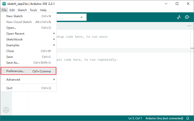
Launch Arduino IDE 2.0 and navigate to File > Preferences….
Copy and paste the following URL into the Additional boards manager URLs field (separate multiple URLs with commas).
https://espressif.github.io/arduino-esp32/package_esp32_index.json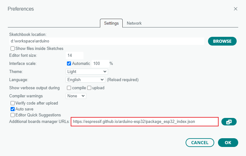
The Arduino ESP32 core package is officially maintained by Espressif:
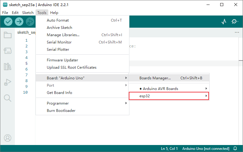
Click the board manager icon on the left sidebar, or select the menu Tools > Board > Boards Manager…, search for "esp32", locate
esp32 by Espressif Systems, and click INSTALL.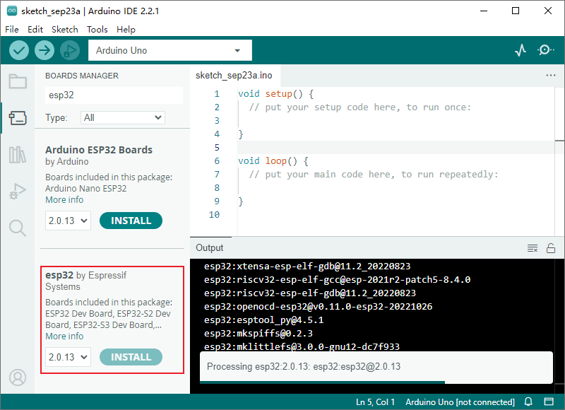
After installation, you can see the esp32 option in the menu Tools > Board.
Compiling and Uploading the Camera Example
Connect the development board to your computer via USB port. If the board does not have an integrated USB-to-Serial chip, use an external USB-to-Serial adapter.
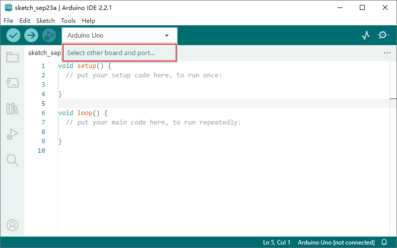
Click the board selection dropdown in the top toolbar and choose Select other board and port… to open the board selection dialog.
Search for "esp32", select ESP32 Wrover Module, and specify the serial port connected to the board.
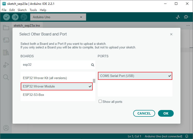
- ESP32 Wrover Module is a general option for esp32 development boards; you can select a specific model if it is available in the list.
- The system should automatically detect the serial port and show it in the PORTS list. If it does not appear, you may need to manually install the appropriate USB-to-Serial driver.
Navigate to File > Examples > ESP32 > Camera > CameraWebServer to open the camera example project.
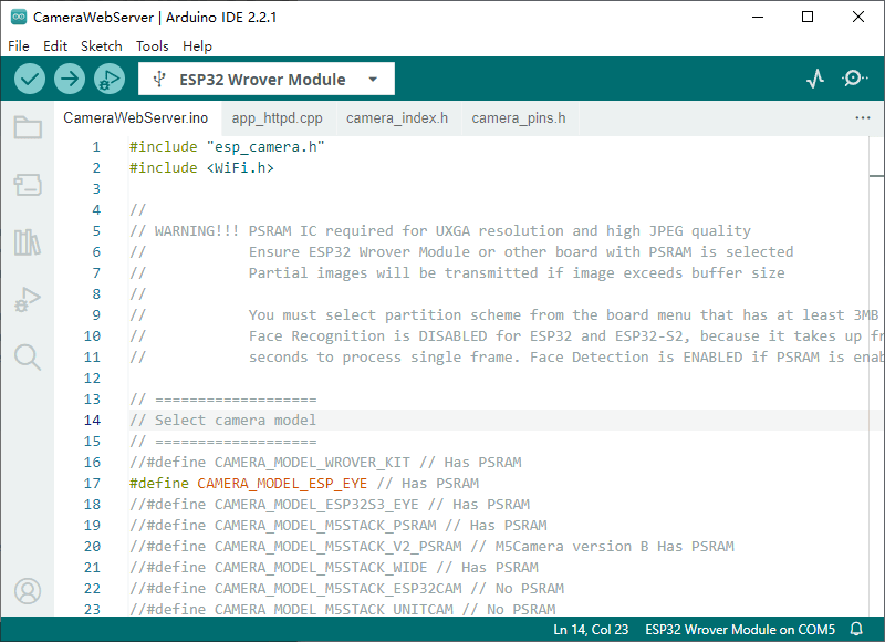
Switch to the
CameraWebServer.inofile. In theSelect camera modesection of the code, uncomment the definition corresponding to your board to specify the pin configurations predefined incamera_pins.h.Alternatively, you can manually define the pins. Using the Camera-1 board as an example, the custom pins are:
cpp//#include "camera_pins.h" // Node-Matrix Camera-1 pin assignment #define PWDN_GPIO_NUM -1 #define RESET_GPIO_NUM -1 #define XCLK_GPIO_NUM 0 #define SIOD_GPIO_NUM 19 #define SIOC_GPIO_NUM 18 #define Y9_GPIO_NUM 38 #define Y8_GPIO_NUM 37 #define Y7_GPIO_NUM 36 #define Y6_GPIO_NUM 25 #define Y5_GPIO_NUM 34 #define Y4_GPIO_NUM 13 #define Y3_GPIO_NUM 12 #define Y2_GPIO_NUM 35 #define VSYNC_GPIO_NUM 5 #define HREF_GPIO_NUM 39 #define PCLK_GPIO_NUM 26- Ensure only one board model is uncommented, all others must remain commented out.
- When using custom pins, you can comment out the
#include "camera_pins.h"line.
In the
Enter your WiFi credentialssection ofCameraWebServer.ino, update thessidandpasswordwith your network settings.cpp// =========================== // Enter your WiFi credentials // =========================== const char* ssid = "my_wifi_ssid"; const char* password = "my_wifi_password";Configure the parameters in the Tools menu based on your board’s hardware configuration. For example, the parameters for Camera-1 are as follows:
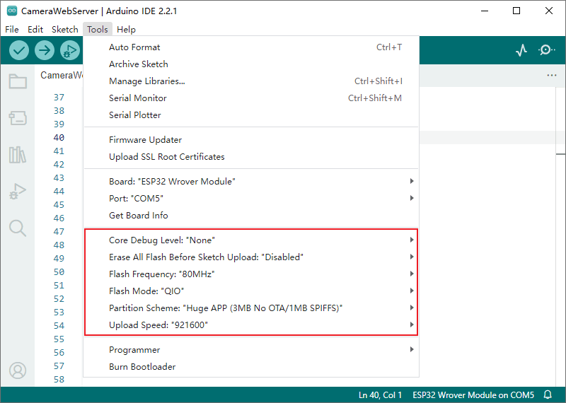
For detailed parameter explanations, refer to the official Espressif documentation:
https://docs.espressif.com/projects/arduino-esp32/en/latest/guides/tools_menu.html
Save the project and click the upload button in the toolbar to compile and upload the code to your board. This may take anywhere from a few seconds to a minute depending on your computer's performance.
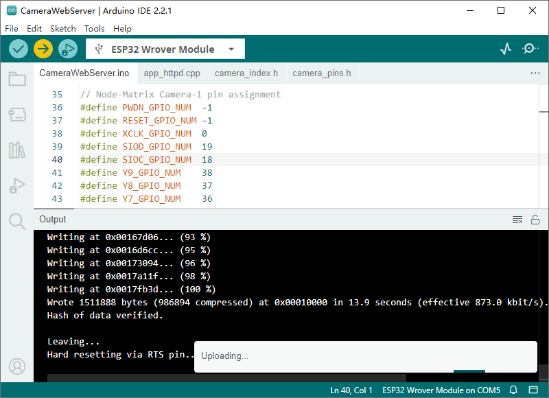
- Boards supporting auto-upload (like Node-Matrix Camera-1) require no further action, simply wait for the process to finish.
- For boards without auto-upload, you must manually enter upload mode (bootloader mode):
- Pull the GPIO_0 pin to low (hold the BOOT button or jumper GPIO_0 to GND).
- While holding GPIO_0 low, press the RST button or cycle the power to reset.
- The board is now in upload mode. You can then click the upload button in the IDE toolbar.
Click the serial monitor button on the right side of the toolbar to open the serial monitor. Reset the board to view the boot logs.
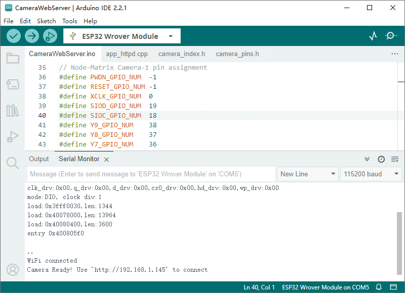
If the logs end with a continuous string of
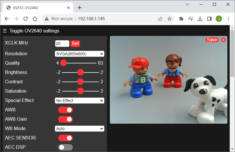
......, it means the network connection failed. Please verify the WiFi settings in step 6.Locate the HTTP service URL in the final line of the boot logs. Copy and paste this URL into a web browser to access the camera's web interface.
Further Steps
The HTTP server code in app_httpd.cpp is quite complex. For a simpler starting point, we provide a simplified example on GitHub.
This concludes the quick start guide for ESP32 camera development using Arduino IDE 2.0. Additional ESP32 examples are available in the examples library under File > Examples > ESP32.