The Arduino IDE is a popular development platform for makers. By installing extension packages, the Arduino IDE can support various board architectures, including the popular ESP series. The new Arduino IDE 2.0 uses a different underlying platform from the classic version and includes more modern IDE features such as improved syntax highlighting, auto-completion, code navigation, and online debugging. The process of installing extension packages in Arduino IDE 2.0 is similar to that in the classic IDE, allowing users to easily transition to the new version.
Installing Arduino IDE 2.0
Go to the Arduino official website to download the version suitable for your operating system.
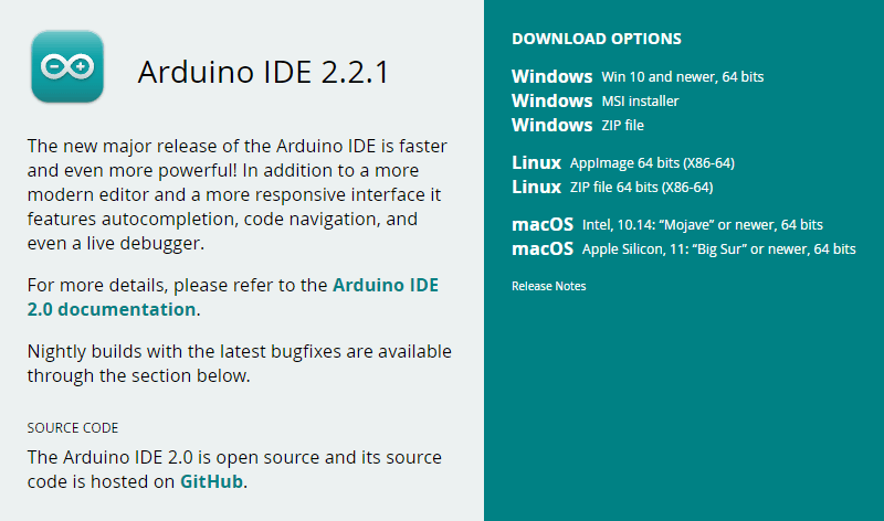
Install it as usual. If you have any questions, please refer to the Arduino Installation Guide on the official website.
Installing the ESP32 Extension Package
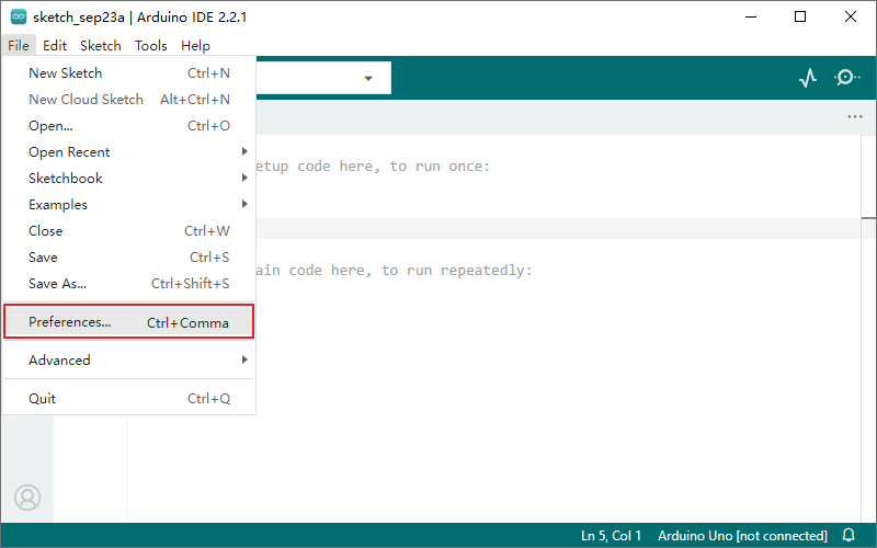
1. Run Arduino IDE 2.0, select the menu File > Preferences…
2. Copy and paste the following URL into the Additional boards manager URLs field (separate multiple URLs with commas).
https://espressif.github.io/arduino-esp32/package_esp32_index.json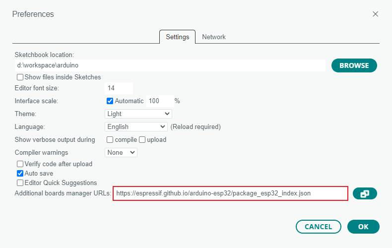
The Arduino ESP32 extension package is officially maintained by Espressif: https://espressif.github.io/arduino-esp32/
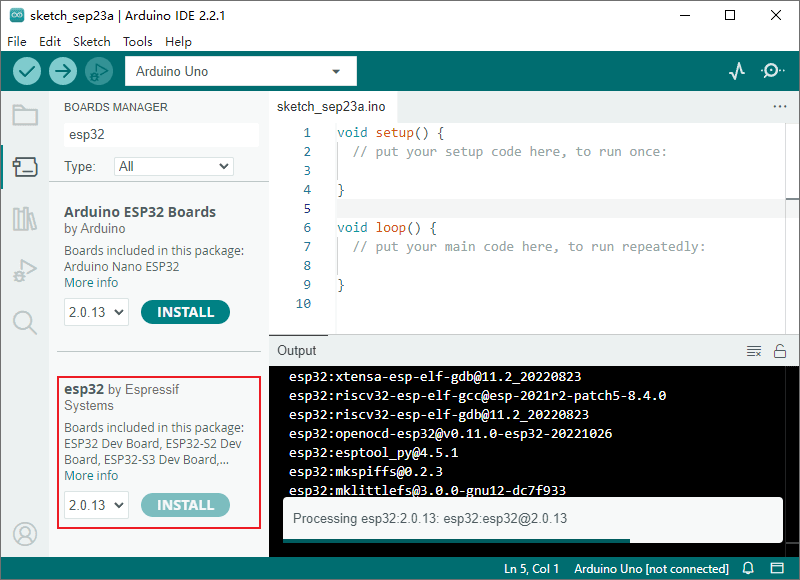
3. Click the board manager icon on the left sidebar, or select the menu Tools > Board > Boards Manager…, search for esp32, find esp32 by Espressif Systems, and click INSTALL.
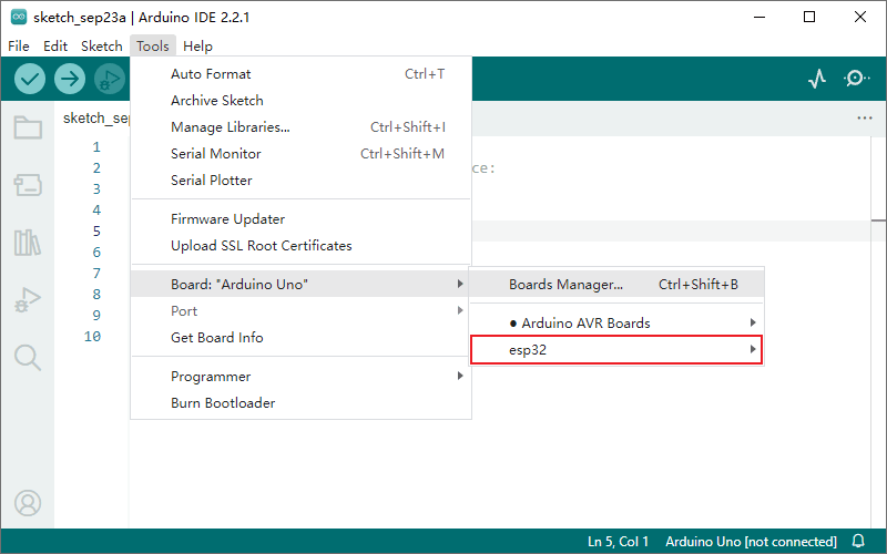
After installation, you can see the esp32 option in the menu Tools > Board.
Compiling and Uploading the Camera Example
1. Connect the development board to your computer’s USB port. If the board doesn’t have an integrated USB serial port, use a USB-to-serial adapter.
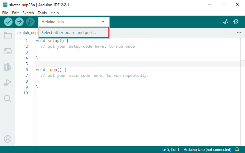
2. Click the board selection drop-down at the top of the toolbar, and select Select other board and port… to open the board selection dialog.
3. Search for esp32, select ESP32 Wrover Module, and choose the corresponding serial port.
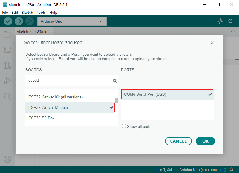
ESP32 Wrover Module is a general option for esp32 development boards. For specific boards, select the corresponding model, if available.
Once the board is connected to the computer’s USB port, the system will automatically recognize the serial port and display it in the PORTS list. If the serial port is not displayed, try manually installing the corresponding USB serial drivers.
4. Select the menu File > Examples > ESP32 > Camera > CameraWebServer to open the camera example project.
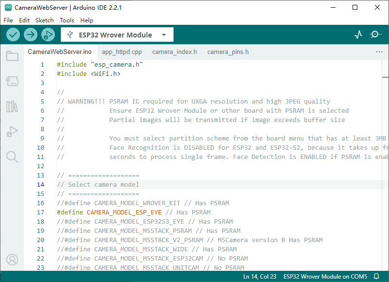
5. Switch to the CameraWebServer.ino file. In the Select camera mode section of the code, uncomment the appropriate definition for your board to specify the camera pins, which are predefined in camera_pins.h. You can also define your own camera pins. For example, on the Camera-1 board, you would set them as follows:
//#include "camera_pins.h"

// Node-Matrix Camera-1 pin assignment
#define PWDN_GPIO_NUM  -1
#define RESET_GPIO_NUM -1
#define XCLK_GPIO_NUM  0
#define SIOD_GPIO_NUM  19
#define SIOC_GPIO_NUM  18
#define Y9_GPIO_NUM    38
#define Y8_GPIO_NUM    37
#define Y7_GPIO_NUM    36
#define Y6_GPIO_NUM    25
#define Y5_GPIO_NUM    34
#define Y4_GPIO_NUM    13
#define Y3_GPIO_NUM    12
#define Y2_GPIO_NUM    35
#define VSYNC_GPIO_NUM 5
#define HREF_GPIO_NUM  39
#define PCLK_GPIO_NUM 26Make sure only one board definition is uncommented at a time. When using custom pins, you can comment out the
#include "camera_pins.h"line.
6. In the Enter your WiFi credentials section of the CameraWebServer.ino file, enter your actual WiFi ssid and password.
// ===========================
// Enter your WiFi credentials
// ===========================
const char* ssid = "my_wifi_ssid";
const char* password = "my_wifi_password";7. Configure the relevant parameters in the Tools menu according to your board’s hardware configuration. For example, the parameters for Camera-1 are as follows:
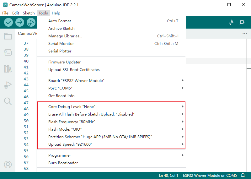
Refer to the Espressif official documentation for parameter details:
https://docs.espressif.com/projects/arduino-esp32/en/latest/guides/tools_menu.html
8. Save the project and click the upload button in the toolbar to compile and upload the code to your board. This process might take tens of seconds depending on your computer’s performance.

For boards with automatic upload (e.g., Node-Matrix Camera-1), this process completes automatically. For boards that do not support automatic upload, you need to manually put the board into bootloader mode as follows:
- Set the GPIO_0 pin to low level. This can be done by pressing the button marked BOOT or connecting GPIO_0 to GND.
- While holding GPIO_0 low, press the button marked RST or let the board power on and reset.
- The board is now in upload mode. You can then click the upload button in the IDE toolbar.
9. Click the serial monitor button on the right side of the toolbar to open the serial monitor. Reset the board, and the serial monitor will display the boot messages.
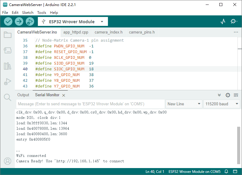
If the monitor continuously outputs
......at the end of the boot messages, it means the network cannot be connected. Verify your WiFi configuration in step 6.
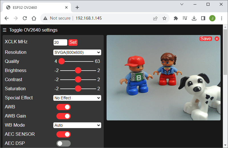
10. Find the HTTP service URL in the boot messages (the last line), open a browser, enter the URL in the address bar, and you will see the camera’s web page.
Further Steps
The server-side code file for the camera example is app_httpd.cpp, which is relatively complex. We provide a simplified example on GitHub for reference.
This is a quick guide on using Arduino IDE 2.0 to develop ESP32 camera modules. You can learn more about using the ESP32 in the examples library (File > Examples > ESP32).